Difference between revisions of "20ma current loop to RS-232 conversion"
(Added detail of tty - RS232 board and terminal strips.) |
(→Schematic 1.1: added sub section headings) |
||
| (5 intermediate revisions by the same user not shown) | |||
| Line 8: | Line 8: | ||
[[File:TTY RS-232 Back.png|400px]] | [[File:TTY RS-232 Back.png|400px]] | ||
| − | == | + | ==Additional Resources== |
| + | * Helpful article, [http://www.vintagecomputer.net/teletype101.cfm Teletype 101] from vintagecomputer.net | ||
* Another circuit. From [[http://altairclone.com/teletype.htm Altairclone]] Specifically designed to fit in a Teletype model 33 using only a 12vdc wall wart for power. | * Another circuit. From [[http://altairclone.com/teletype.htm Altairclone]] Specifically designed to fit in a Teletype model 33 using only a 12vdc wall wart for power. | ||
| − | * Another [https://www.circuitlab.com/circuit/mnartk/screenshot/1024x768/ circuit] I found referenced on the greenkeys email list | + | * Another [https://www.circuitlab.com/circuit/mnartk/screenshot/1024x768/ circuit] I found referenced on the greenkeys email list |
==My ASR hookup== | ==My ASR hookup== | ||
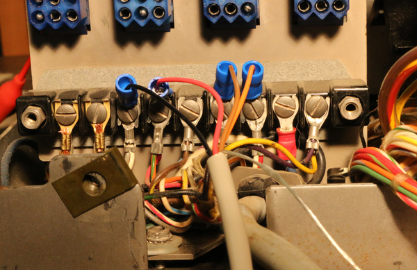
I built the circuit described above from the altairclone site. I found the Teletype 101 article helpful for identifying the proper terminal strip locations. The interface works. I set baud to 110, with 7 bits and 'mark' parity in TeraTerm on a windows 8 notebook with a Gigaware USB<> serial convereter. | I built the circuit described above from the altairclone site. I found the Teletype 101 article helpful for identifying the proper terminal strip locations. The interface works. I set baud to 110, with 7 bits and 'mark' parity in TeraTerm on a windows 8 notebook with a Gigaware USB<> serial convereter. | ||
| + | ===Schematic 1.1=== | ||
| + | From the original schematic at altairclone I added ASR terminal strip location numbers. | ||
| + | |||
| + | [[File:RS-232 to ASR-33 Teletype Interface Schematic v1.1.jpg]] | ||
| + | ===Wiring legend=== | ||
<source lang="text"> | <source lang="text"> | ||
| − | Signal | + | screw wire schematic |
| + | Signal terminal color connection | ||
| + | (Teletype 101 nomenclature) (on ASR) (mine) (altair clone nomenclature) | ||
--------------------------------------------------------------------- | --------------------------------------------------------------------- | ||
| − | Transmitted data send (+) | + | Transmitted data send (+) 7 orange Data to Teletype + |
| − | Transmitted data return (-) | + | Transmitted data return (-) 6 brown Data to Teletype - |
| − | Received data send (+) | + | Received data send (+) 4 red Data from Teletype + |
| − | Received data return (-) | + | Received data return (-) 3 black Data from Teletype - |
</source> | </source> | ||
| − | + | ===Image details=== | |
[[File:My Altairclone TTY-RS232 Interface.png|600px]] | [[File:My Altairclone TTY-RS232 Interface.png|600px]] | ||
[[File:Teletype Model 33 ASR terminal block.png|600px]] | [[File:Teletype Model 33 ASR terminal block.png|600px]] | ||
| Line 31: | Line 39: | ||
[[Category:Various]] | [[Category:Various]] | ||
[[Category:Teletype]] | [[Category:Teletype]] | ||
| + | [[Category:Operational]] | ||
Latest revision as of 09:36, 21 August 2015
Contents
20ma current loop <> RS-232 conversion
Vintage PCB
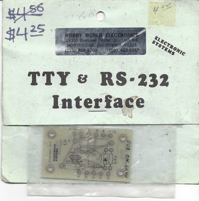
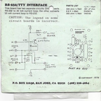
Dig this crazy circuit board man! Still in it's original packaging from Hobby World Electronics in Northridge California.
Additional Resources
- Helpful article, Teletype 101 from vintagecomputer.net
- Another circuit. From [Altairclone] Specifically designed to fit in a Teletype model 33 using only a 12vdc wall wart for power.
- Another circuit I found referenced on the greenkeys email list
My ASR hookup
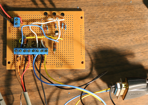
I built the circuit described above from the altairclone site. I found the Teletype 101 article helpful for identifying the proper terminal strip locations. The interface works. I set baud to 110, with 7 bits and 'mark' parity in TeraTerm on a windows 8 notebook with a Gigaware USB<> serial convereter.
Schematic 1.1
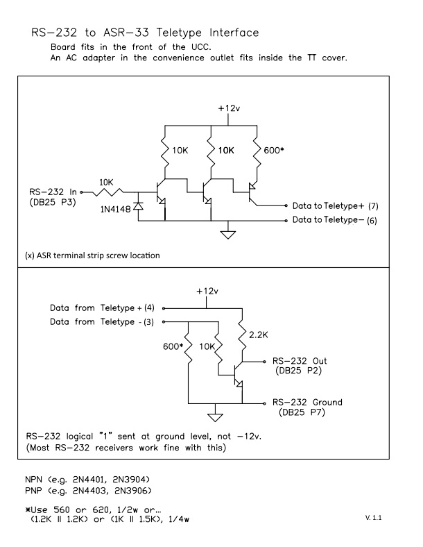
From the original schematic at altairclone I added ASR terminal strip location numbers.
Wiring legend
                               screw        wire              schematic
Signal                        terminal      color             connection
(Teletype 101 nomenclature)   (on ASR)      (mine)          (altair clone nomenclature)
---------------------------------------------------------------------
Transmitted data send (+)        7          orange          Data to Teletype +
Transmitted data return (-)      6          brown           Data to Teletype -

Received data send (+)           4          red             Data from Teletype +
Received data return (-)         3          black           Data from Teletype -
