Difference between revisions of "Teletype Model 33"
(Add Wayne Text) |
(→Notes from Wayne ?callsign?: add KB1FDW) |
||
| Line 2: | Line 2: | ||
| − | ==Notes from Wayne | + | ==Notes from Wayne KB1FDW== |
===Image Gallery=== | ===Image Gallery=== | ||
<gallery> | <gallery> | ||
Revision as of 18:17, 10 March 2019
Some repair notes gleaned from the GreenKeys emaillist
Contents
Notes from Wayne KB1FDW
Image Gallery
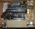
Top Cover Removed
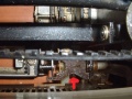
H Plate installed
tab properly installed
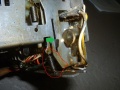
Kybd reset lever in reset position (green arrow) and spring (red circle)
reset lever tripped
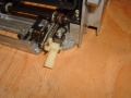
Oil pad in place.JPG
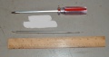
Printer removal tools


_and_spring_(red_circle).JPG)


32/33 ASR Cover Removal
To remove the cover, do the following:
Unplug the AC power. Close the clear plastic tape reader lid as though there was a tape in it. Push the tape reader handle to Start or Stop, never FREE. Remove the platen knob. Remove the paper and tape by tearing or cutting it. Lift the paper roll out of the cover to lighten the cover some. Remove the 3 rear thumbscrews. Remove the Line/Off/Local knob. It pulls straight off. Sometimes you have to use a screwdriver to carefully pry it off. Pull down and out gently on the bottom of the front plate. It will fall off in your hands. Remove the 4 screws in the front of the cover. There may be a small screw in the left side of the tape reader cover. If it has a head on it, remove it. If its just a stud, you can just pull the cover away from the stud as you lift the cover off.
Some covers had slots instead of holes in the main cover. If your cover is slotted, just loosen the 7 screws about halfway out.
When you remove the cover, go slow and carefully straight up. Watch the tape reader as you remove the cover. Its most prone to damage removing and replacing the cover. Thats why you move the TR handle to Start or Stop and close the lid. When you replace the cover, again, watch the TR carefully as you replace it. The cover should go on easily with a little jiggling to help it fall into place. If you have a dial or push buttons in the electronics, you will have to guide them into place. Check all around to be sure the cover is fully in place before replacing cover screws. If your keyboard cover has some latching or fitting tabs make sure the main cover is latched on them. The front of the cover may need a little pressure downward in places before you tighten the 4 screws. Slide the front plate back on till it clicks in to the little pan tabs. Replace the platen knob and power knob. Paper feeds off the bottom of the roll and tape off the top.
Removing And Re-Installing A 32 or 33 Printer
All electrical connections are easy. No notes need to be taken except on a sprocket feed 33.
You will need the following tools: A 10” long medium flat blade screwdriver and a long handle screw starter to hold the H plate when you re-install it.
The carriage must be all the way to the left inside the dashpot and the machine must be unplugged from the AC power.
Remove the 2 slide on connections above the “Caution High Voltage” plastic insulator. Leave the cable in the slide on clip. Just remove the clip from the frame. On sprocket feed machines, note the color code of the 3 slide on connections just above the previous slide ons and then remove them.
Next, remove Molex plug #4 and #8. On some 33's you will have to remove #3 Molex as well.
Remove the braided ground wire that slides onto the slip on connector mounted to the rear of the call control unit. Position the wiring away from the printer and call control unit.
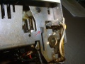
Locate the H plate and with the screwdriver inserted in the H plate middle opening slot, push left against the printer spring until the plate is out of the keyboard reset lever. This is one of the few times on a 33 where it is sometimes necessary to use a little force to move the printer to the left to allow the H plate to come all the way out of the keyboard side. Dont push on the H plate, just push left on the front carriage bar if needed. Remove H plate from machine noting its orientation for reassembly.
The tricky part: Left hand (2 or 3 fingers) under the silver frame rod just in front of the motor fuse and right hand under the right side of the platen, lift the rear of the printer up about an inch or two. Then while watching the H plate area, lift the front of the printer up just enough to remove it from the rubber cushions it sits on and move the entire printer just an inch or two to the left and then to the rear and out of the pan.
To re-install the printer, reverse the above directions. The tricky part is to make sure the white “Here Is” tab goes under the lower extension of the “Here Is” keyboard key. Before installing make sure this extension is not bent. You should be watching this area as you set the printer back into its rubber cushion mounts.
Lift the rear and front of the printer slightly to make sure its in all 4 rubber cushions. It should look square to the pan, not angled.
Put the H plate on the long screw starter and lower it into the printer where you removed it. The big indent should be to the left and the flat indent towards the keyboard. For now, just get the H plate into the printer side of the H plate home. Remove the screw starter, leaving the H plate installed to the printer side. Next put the screwdriver in the H plate center slot and push the plate against the printer spring and get it positioned so at least one of the H plate fingers is in or nearly in the keyboard reset lever. Sometimes you can hit any keyboard character and rotate the motor fan towards the front and the H plate will slip into its keyboard home. Also sometimes the H plate will slide into the keyboard reset lever, but the printer spring will be jammed to the left. Carefully jiggle the spring area until the mechanism is free. Do not apply exessive force.
Put all the electrical connectors back on starting with the printer ground.
You must go very carefully when removing or re-installing the printer so as not to bend the Here Is extension or knock the Here Is white tab out of its holder.
If you can remove and re-install the printer successfully, then all the other work you do on a 33 will be easily available to you.
Assembly Instructions for 32 and 33 ASR Teletype
Remove the back panel from the pedestal. Pick up the teletype from the back and place it onto the pedestal from the rear turned about 45 degrees to the right. It should be balanced OK. Have the 4 assembly screws and washers handy. The screws should go in easily. If not, reverse and try again. You will be installing the screw and washer into the hole that is closest to you and to your left first. Its not the one that you would expect to use, but slightly closer to the front. Carefully move the teletype until you can see the screw hole line up as you look up from inside the pedestal. Install and tighten this screw all the way and then loosen it one turn. Lift the teletype slightly and rotate CCW to sit squarely on the pedestal until you can see the other 3 holes line up. Install the other 3 screws. Don’t forget to tighten the first one fully, but do not over tighten these screws. They are going into plastic nuts. The back of the teletype sits directly above the stand. It does not protrude out.
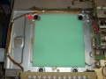
Install the tape reader PS inside the pedestal favoring the left side so the cable with the Molex connector can reach it. The PS slides onto the front top lip of the pedestal. When you plug in the Molex connector, support the circuit board with your fingers so as not to damage the board. The chad box slides on from the front below the tape punch.
If you need to reinstall the paper, it should feed from the bottom of the roll. Raise the lid w/window and pull the paper release toward you. Fold the paper and slide it in. Lift the front wire guide and feed the paper under it. Lower the guide. Leaving the paper released, close the lid and pull the paper thru and up to the roll and align it for even left and right spacing on the printer platen and with the roll. You will waste some paper doing this correctly. Then return the paper release to normal. Remove the pipe cleaner that holds the carriage to the left if one has been installed. If you need to reinstall the ribbon, it feeds off the outside of the spool thru the reversing fingers and into the guide behind the typewheel, but not behind the chrome paper fingers that rest on the paper in the platen. Make sure the ribbon spools are fully on by turning them slightly while holding the notched black ribbon spool holder that the ribbon spools sit on. If you need to reinstall the paper tape, it feeds off the top of the roll. Cut it on a slight angle and I find it easier to install if you remove the 4 button tape punch cover so you can see what is happening. The cover pulls off if you start with the rear side. Don’t feed any tape with glue or cellophane residue. Gently push the tape into the punch until it contacts the feed wheel. Turn the teletype ON to Local. Hit some deletes or any key to feed the tape thru the punch. If it jams, press the tape release button and pull the tape back out and start over. As the tape first comes out of the punch block gently hold it to the left for a couple of characters to help center it in the punch block. When successful, replace the tape punch cover.
Punch a line of tape with a leader and trailer and load it in the reader to test it. It will install best if the reader control is in FREE position. Then START on the tape reader control lever to run the tape. When not in use turn the TTY to OFF to save wear on the gears, belt and mainshaft bearings. Do not leave teletype AC plugged-in unattended for long periods of time or overnight. Even with the motor off, the electronics are on and there will eventually be heat damage to the SMD card or even a possibility of fire.