Difference between revisions of "Cromemco 8K Bytesaver"
(changed category from s-100 to s-100 Boards) |
(→Resources: add category ME2700) |
||
| (4 intermediate revisions by the same user not shown) | |||
| Line 8: | Line 8: | ||
Here is the .PRN file from a simple program I loaded into a 2708 to test my ability to program an EPROM with Martin Eberhard’s post era ME2700 Orphan EPROM Programmer. On my Imsai front panel I examined the address C000 then pressed run. Yup the programmed output LEDs change state based on the programmed input paddle switches. | Here is the .PRN file from a simple program I loaded into a 2708 to test my ability to program an EPROM with Martin Eberhard’s post era ME2700 Orphan EPROM Programmer. On my Imsai front panel I examined the address C000 then pressed run. Yup the programmed output LEDs change state based on the programmed input paddle switches. | ||
| − | |||
| − | |||
<source lang="text"> | <source lang="text"> | ||
| Line 25: | Line 23: | ||
</source> | </source> | ||
| + | ==Resources== | ||
| + | * ME2700 EPROM programmer firmware and documentation located [https://drive.google.com/folderview?id=0B-XdfCubTNJJRnB2cXpQM1RBMWs&usp=drive_web here.] | ||
| + | * Martin Eberhard [https://drive.google.com/drive/folders/0B-XdfCubTNJJNW54UWJJVnpKMlE MEMON80] Rev. 1.1 | ||
| + | |||
| + | Now it's off to find a simple monitor program to load in EPROM(s) and decide which I/O card to use for serial communications. | ||
| Line 30: | Line 33: | ||
[[Category:S-100 Boards]] | [[Category:S-100 Boards]] | ||
[[Category:Operational]] | [[Category:Operational]] | ||
| + | [[Category:Martin Eberhard]] | ||
| + | [[Category:ME2700]] | ||
Latest revision as of 16:04, 10 August 2018
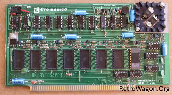
Cromemco 8K Bytesaver EPROM board. Working. My dad and I each built one of these. I think this one was mine.
Here is the .PRN file from a simple program I loaded into a 2708 to test my ability to program an EPROM with Martin Eberhard’s post era ME2700 Orphan EPROM Programmer. On my Imsai front panel I examined the address C000 then pressed run. Yup the programmed output LEDs change state based on the programmed input paddle switches.
                ; jha 2/10/2016 !Light data LED for corresponding switch
                ; ImsaiTp1.asm Imsai Test Program 1 from pp. 35. of Imsai documentation.

                START:
 C000           		org		0c000h

                LOOP:
 C000 DBFF      		in		0FFh
 C002 D3FF      		out		0FFh
 C004 C300C0    		jmp		LOOP
 C007                   end
Resources
Now it's off to find a simple monitor program to load in EPROM(s) and decide which I/O card to use for serial communications.
