Difference between revisions of "Ademco 685"
(initial creation) |
(→Resources: added heading so Moss monitor shows in menu) |
||
| (6 intermediate revisions by the same user not shown) | |||
| Line 10: | Line 10: | ||
I installed a set of CCS boards and successfully booted from 8" FDD at both 2 and 4 mhz. I tried a CompuPro set without success. Interesting that I haven't made the CCS board set work on the CompuPro chassis. Buss termination needs more experimentation. | I installed a set of CCS boards and successfully booted from 8" FDD at both 2 and 4 mhz. I tried a CompuPro set without success. Interesting that I haven't made the CCS board set work on the CompuPro chassis. Buss termination needs more experimentation. | ||
| + | ==Resources== | ||
| + | ===[[CCS Z-80 CPU Model 2810A|CCS 2810]] page with links to Moss 2.2 monitor code.=== | ||
| + | |||
| + | ==Cabinetry== | ||
[[File:Ademco685PaletSideFrontView.jpg|600px]] | [[File:Ademco685PaletSideFrontView.jpg|600px]] | ||
[[File:Ademco685PaletSideRearView.jpg|600px]] | [[File:Ademco685PaletSideRearView.jpg|600px]] | ||
| + | |||
| + | ==Inside== | ||
| + | |||
| + | If you look closely you'll see that the S-100 edge connector spacing is not consistent. I didn't measure, but a board set fits in the slots that are closer together. | ||
[[File:Ademco685TopView.jpg|600px]] | [[File:Ademco685TopView.jpg|600px]] | ||
| Line 20: | Line 28: | ||
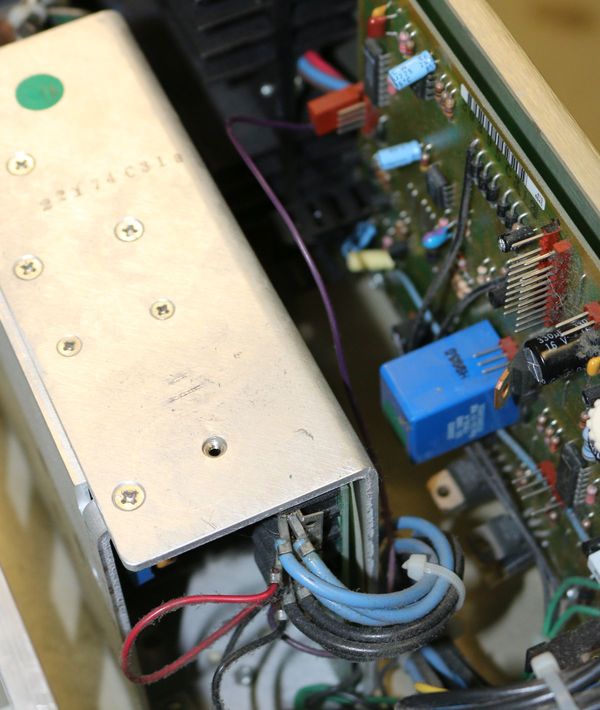
I've cut away the wire harness. There is a single purple wire to leave between the aluminum supply within the main supply that goes to the PCB mounted against the outer wall of the chassis. | I've cut away the wire harness. There is a single purple wire to leave between the aluminum supply within the main supply that goes to the PCB mounted against the outer wall of the chassis. | ||
| + | ===Power supply detail=== | ||
[[File:Ademco685PwrSplyDetail.jpg|600px]] | [[File:Ademco685PwrSplyDetail.jpg|600px]] | ||
Leave this purple wire. | Leave this purple wire. | ||
| + | ==Rear view== | ||
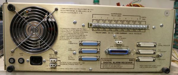
[[File:Ademco685RearView.jpg|600px]] | [[File:Ademco685RearView.jpg|600px]] | ||
| + | ==Front face== | ||
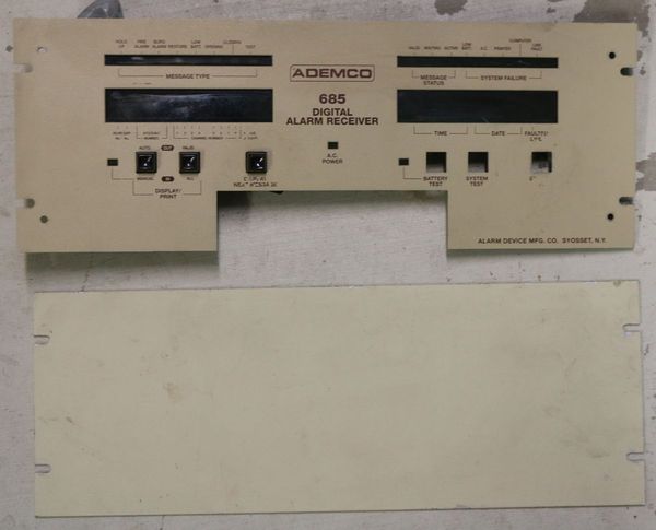
| + | [[File:Ademco685FrontFacePlate.jpg|600px]] | ||
| + | ===Cover=== | ||
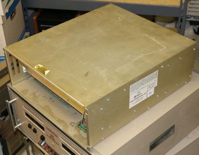
| + | The inner box does have a cover. | ||
| − | [[File: | + | [[File:Ademco685TopCover.jpg|400px]] |
A standard rack mount plate can easily replace the front panel. Drill 4our holes to attach to chassis. | A standard rack mount plate can easily replace the front panel. Drill 4our holes to attach to chassis. | ||
| + | ==Salvagable== | ||
| + | I like the VFD. I looked around on the boards for a VFD controller which I didn't find. There are a couple 27C256 EPROMs too. | ||
| + | ===Vacuum Fluorescent Display=== | ||
| + | [[File:VFD.jpg|400px]] | ||
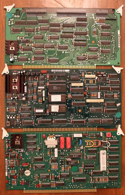
| + | ===Boards=== | ||
| + | Aside from the CCS CPU the unit I dissembled had these boards. | ||
| + | |||
| + | [[File:Ademco685Boards.jpg|400px]] | ||
Latest revision as of 01:05, 17 September 2016
Ademco 685 Digital Alarm Receiver
the stealth S-100 chassis
Provision for battery backup
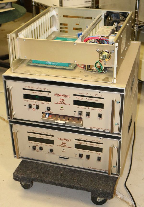
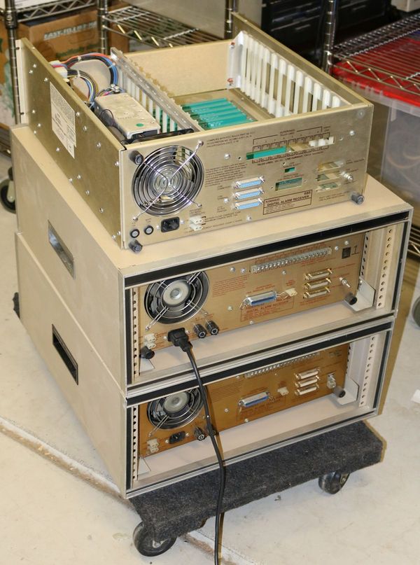
This alarm is built on a S-100 Chassis. It comes with a California Computer Systems (CCS) 2810 2 / 4 mhz switchable Z80 CPU. It doesn't have the CMOS EPROM installed however I burnt one from a copy of my existing CCS system, changed a couple jumpers and there we go a nice auto bauding serial console with a ROM Monitor. Get a feel for the size of the enclosure for this if not rack mounted. This is the chassis after I striped it of an unnecessary wiring harness. The chassis removed from the enclosure weights in at 20 pounds where a CompuPro desktop weights 32 pounds. I measured the DC supply at 9.18, 14.22 and -15.8 I see a bunch on ePay and have seen them on Craigslist too.
I installed a set of CCS boards and successfully booted from 8" FDD at both 2 and 4 mhz. I tried a CompuPro set without success. Interesting that I haven't made the CCS board set work on the CompuPro chassis. Buss termination needs more experimentation.
Contents
Resources
CCS 2810 page with links to Moss 2.2 monitor code.
Cabinetry
Inside
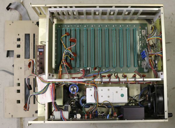
If you look closely you'll see that the S-100 edge connector spacing is not consistent. I didn't measure, but a board set fits in the slots that are closer together.
I've cut away the wire harness. There is a single purple wire to leave between the aluminum supply within the main supply that goes to the PCB mounted against the outer wall of the chassis.
Power supply detail
Leave this purple wire.
Rear view
Front face
Cover
The inner box does have a cover.
A standard rack mount plate can easily replace the front panel. Drill 4our holes to attach to chassis.
Salvagable
I like the VFD. I looked around on the boards for a VFD controller which I didn't find. There are a couple 27C256 EPROMs too.
Vacuum Fluorescent Display
Boards
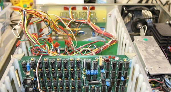
Aside from the CCS CPU the unit I dissembled had these boards.
