Teletype Model 33
Some repair notes gleaned from the GreenKeys emaillist
Remember Wayne's advice; "Most 32/33 problems can be found visually and don't take the keyboard apart when you first get the machine. The machine must have 3 printer shipping screws installed if its to be shipped. 10/32 x 1 inch with flat washers. Always ship Fed Ex Ground, never the brown guys. Also, many troubles on 33's that have not been run in a long time are due to congealed grease or oil"
Contents
- 1 Notes from Wayne KB1FDW
- 1.1 Image Gallery
- 1.2 32/33 differences
- 1.3 32/33 ASR Cover Removal
- 1.4 Removing And Re-Installing A 32 or 33 Printer
- 1.5 Replacing a typewheel
- 1.6 Replacing a vinyl hammer
- 1.7 Assembly Instructions for 32 and 33 ASR Teletype
- 1.8 32 and 33 Belt Replacing
- 1.9 BASIC MAINTENANCE OF A 32/33 MACHINE
- 1.10 Line and Local relay work
- 1.11 32/33 Speed Gear Replacement
- 1.12 Replacing a 32/33 ASR keyboard
- 1.13 Testing running open
- 2 Resources
Notes from Wayne KB1FDW
Image Gallery
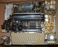
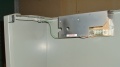
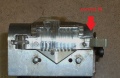
Top Cover Removed
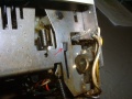
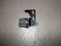
H Plate installed
tab properly installed
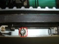
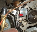
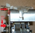
Kybd reset lever in reset position (green arrow) and spring (red circle)
reset lever tripped
Oil pad in place.JPG
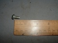
pedestal to TTY screw 1 quarter by 14, self
serial number, carriage spring removed
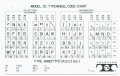
typewheel code chart
Answerback
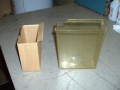
Chad box and cardboard sub
Distributor Faceplate
EOL stop clip
Front printer shipping screw location
LF sub 2
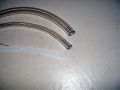
LF sub tubing
LF sub
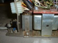
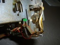
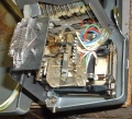
Line Local Relay Location
Line Local Relay removed for inspection

Manual CR lever RED and enable spacing lever BLUE
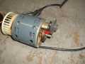
Motor oil hole A
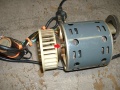
Motor oil hole B
No tape
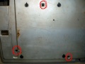
Pedestal holes used for 33 mount
Printer shipping screws location from underside
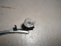
Rangefinder semi-captive plastic nut
Rangefinder pointer
Tape loaded
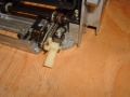
Tape punch spindle sub 1.5 inch ID PVC cut 3/8ths long
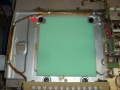
Tape reader power supply in pedestal
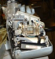
Top View
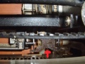
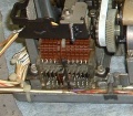
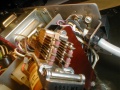
TR pulsing area
UCC-6 FS 1 Receive all on one page
Tape reader latch top view
Tape reader latch


_and_spring_(red_circle).JPG)


32/33 differences
Tape Reader


32/33 ASR Cover Removal
To remove the cover, do the following:
Unplug the AC power. Close the clear plastic tape reader lid as though there was a tape in it. Push the tape reader handle to Start or Stop, never FREE. Remove the platen knob. Remove the paper and tape by tearing or cutting it. Lift the paper roll out of the cover to lighten the cover some. Remove the 3 rear thumbscrews. Remove the Line/Off/Local knob. It pulls straight off. Sometimes you have to use a screwdriver to carefully pry it off. Pull down and out gently on the bottom of the front plate. It will fall off in your hands. Remove the 4 screws in the front of the cover. There may be a small screw in the left side of the tape reader cover. If it has a head on it, remove it. If its just a stud, you can just pull the cover away from the stud as you lift the cover off.
Some covers had slots instead of holes in the main cover. If your cover is slotted, just loosen the 7 screws about halfway out.
When you remove the cover, go slow and carefully straight up. Watch the tape reader as you remove the cover. Its most prone to damage removing and replacing the cover. Thats why you move the TR handle to Start or Stop and close the lid. When you replace the cover, again, watch the TR carefully as you replace it. The cover should go on easily with a little jiggling to help it fall into place. If you have a dial or push buttons in the electronics, you will have to guide them into place. Check all around to be sure the cover is fully in place before replacing cover screws. If your keyboard cover has some latching or fitting tabs make sure the main cover is latched on them. The front of the cover may need a little pressure downward in places before you tighten the 4 screws. Slide the front plate back on till it clicks in to the little pan tabs. Replace the platen knob and power knob. Paper feeds off the bottom of the roll and tape off the top.
Removing And Re-Installing A 32 or 33 Printer
All electrical connections are easy. No notes need to be taken except on a sprocket feed 33.
You will need the following tools: A 10” long medium flat blade screwdriver and a long handle screw starter to hold the H plate when you re-install it.
The carriage must be all the way to the left inside the dashpot and the machine must be unplugged from the AC power.
Remove the 2 slide on connections above the “Caution High Voltage” plastic insulator. Leave the cable in the slide on clip. Just remove the clip from the frame. On sprocket feed machines, note the color code of the 3 slide on connections just above the previous slide ons and then remove them.
Next, remove Molex plug #4 and #8. On some 33's you will have to remove #3 Molex as well.
Remove the braided ground wire that slides onto the slip on connector mounted to the rear of the call control unit. Position the wiring away from the printer and call control unit.
Locate the H plate and with the screwdriver inserted in the H plate middle opening slot, push left against the printer spring until the plate is out of the keyboard reset lever. This is one of the few times on a 33 where it is sometimes necessary to use a little force to move the printer to the left to allow the H plate to come all the way out of the keyboard side. Dont push on the H plate, just push left on the front carriage bar if needed. Remove H plate from machine noting its orientation for reassembly.
The tricky part: Left hand (2 or 3 fingers) under the silver frame rod just in front of the motor fuse and right hand under the right side of the platen, lift the rear of the printer up about an inch or two. Then while watching the H plate area, lift the front of the printer up just enough to remove it from the rubber cushions it sits on and move the entire printer just an inch or two to the left and then to the rear and out of the pan.
To re-install the printer, reverse the above directions. The tricky part is to make sure the white “Here Is” tab goes under the lower extension of the “Here Is” keyboard key. Before installing make sure this extension is not bent. You should be watching this area as you set the printer back into its rubber cushion mounts.
Lift the rear and front of the printer slightly to make sure its in all 4 rubber cushions. It should look square to the pan, not angled.
Put the H plate on the long screw starter and lower it into the printer where you removed it. The big indent should be to the left and the flat indent towards the keyboard. For now, just get the H plate into the printer side of the H plate home. Remove the screw starter, leaving the H plate installed to the printer side. Next put the screwdriver in the H plate center slot and push the plate against the printer spring and get it positioned so at least one of the H plate fingers is in or nearly in the keyboard reset lever. Sometimes you can hit any keyboard character and rotate the motor fan towards the front and the H plate will slip into its keyboard home. Also sometimes the H plate will slide into the keyboard reset lever, but the printer spring will be jammed to the left. Carefully jiggle the spring area until the mechanism is free. Do not apply exessive force.
Put all the electrical connectors back on starting with the printer ground.
You must go very carefully when removing or re-installing the printer so as not to bend the Here Is extension or knock the Here Is white tab out of its holder.
If you can remove and re-install the printer successfully, then all the other work you do on a 33 will be easily available to you.
Replacing a typewheel
When removing your typewheel, be sure to hold on to it with your fingers when removing the nut. If you break the vertical shaft you are in big trouble. You should have the typewheel in home position, machine plugged in but after typing one character, turn off. That puts the wheel in home position. Install the new wheel and just titen the nut snugly. Type ABCDEFG and HIJKLMNOP to see both rotations of the wheel. With nut just loose move the wheel in the right direction to improve the quality of the print. There is some over travel or free play in the mechanism so its a trial and error method. When happy with the print, hold the wheel with your fingers and fully titen the nut. Just a little more than snug.
Replacing a vinyl hammer
Remove the ribbon and clean the debris off the metal hammer. There is a groove around the metal hammer that is square in shape. That has to be very clean. Use a piece of string with solvent on it to fully clean the groove. See pic. Dont remove your metal hammer. The pic is just to show you the groove. Put a little oil on the inside of the vinyl hammer and twist it onto the metal one till it turns freely and no bulges. Try to keep the debris out the the carriage mechanism when cleaning.

Assembly Instructions for 32 and 33 ASR Teletype
Remove the back panel from the pedestal. Pick up the teletype from the back and place it onto the pedestal from the rear turned about 45 degrees to the right. It should be balanced OK. Have the 4 assembly screws and washers handy. The screws should go in easily. If not, reverse and try again. You will be installing the screw and washer into the hole that is closest to you and to your left first. Its not the one that you would expect to use, but slightly closer to the front. Carefully move the teletype until you can see the screw hole line up as you look up from inside the pedestal. Install and tighten this screw all the way and then loosen it one turn. Lift the teletype slightly and rotate CCW to sit squarely on the pedestal until you can see the other 3 holes line up. Install the other 3 screws. Don’t forget to tighten the first one fully, but do not over tighten these screws. They are going into plastic nuts. The back of the teletype sits directly above the stand. It does not protrude out.
Install the tape reader PS inside the pedestal favoring the left side so the cable with the Molex connector can reach it. The PS slides onto the front top lip of the pedestal. When you plug in the Molex connector, support the circuit board with your fingers so as not to damage the board. The chad box slides on from the front below the tape punch.
If you need to reinstall the paper, it should feed from the bottom of the roll. Raise the lid w/window and pull the paper release toward you. Fold the paper and slide it in. Lift the front wire guide and feed the paper under it. Lower the guide. Leaving the paper released, close the lid and pull the paper thru and up to the roll and align it for even left and right spacing on the printer platen and with the roll. You will waste some paper doing this correctly. Then return the paper release to normal. Remove the pipe cleaner that holds the carriage to the left if one has been installed. If you need to reinstall the ribbon, it feeds off the outside of the spool thru the reversing fingers and into the guide behind the typewheel, but not behind the chrome paper fingers that rest on the paper in the platen. Make sure the ribbon spools are fully on by turning them slightly while holding the notched black ribbon spool holder that the ribbon spools sit on. If you need to reinstall the paper tape, it feeds off the top of the roll. Cut it on a slight angle and I find it easier to install if you remove the 4 button tape punch cover so you can see what is happening. The cover pulls off if you start with the rear side. Don’t feed any tape with glue or cellophane residue. Gently push the tape into the punch until it contacts the feed wheel. Turn the teletype ON to Local. Hit some deletes or any key to feed the tape thru the punch. If it jams, press the tape release button and pull the tape back out and start over. As the tape first comes out of the punch block gently hold it to the left for a couple of characters to help center it in the punch block. When successful, replace the tape punch cover.
Punch a line of tape with a leader and trailer and load it in the reader to test it. It will install best if the reader control is in FREE position. Then START on the tape reader control lever to run the tape. When not in use turn the TTY to OFF to save wear on the gears, belt and mainshaft bearings. Do not leave teletype AC plugged-in unattended for long periods of time or overnight. Even with the motor off, the electronics are on and there will eventually be heat damage to the SMD card or even a possibility of fire.
32 and 33 Belt Replacing
Part #A26R 3 047025 at http://sdp-si.com/estore/Catalog About $8 apiece I think. They are white.
Well, its pretty easy. You don't do it by the book. All instructions are while standing in front of the 33.
Most importantly, you trip the distributor clutch by hitting any kybd key or if the printer is removed the lack of the keyboard should have tripped the clutch. That holds the distributo clutch drum in place while you do the work. You don't want it sliding off the shaft to the left or you will have to remove the distributor shaft to get the shoes back into the drum.
Loosen the 4 screws that hold the motor and rock it toward the front of the machine a lot to take the tension off the old belt. Slide the belt off the motor speed gear and twist it to get it fully off and free of the gear. Slide the motor to the left to help if needed.
Now remove the long U shaped trip shaft bar that's just above the middle of the main shaft. The one with the 4 springs on it. Remove it as a unit, holding onto the 4 springs on the bar with both hands and slipping the left side out first, then the right side, then slip the springs off the trip levers. Lay it on the bench as a unit with all springs still attached. Replace later in reverse order.
Remove the right side trip shaft bracket, the one that holds the two bronze bearings in and has the nylon and rubber bushing in it. Remove the two screws that hold it to the printer casting and slide it off the trip shaft to remove. Now slide the left distributor shaft bronze bearing to the left and remove it.
With a little creative twisting of the old belt, maybe with the help of some long nose pliers, you can slip it up and out of the distributor shaft and thru the space left by the bronze bearing you removed.
Install new belt same way. On the distributor shaft and gear first and not the motor speed gear yet.
Slip the bronze gear back on the shaft snugly to the clutch drum that you smartly have captured when you tripped the clutch shoes inside.
Replace the trip shaft bracket. Slide it on the trip shaft and then replace the 2 screws into the casting almost fully tight. The mainshaft bronze bearing should be in centered under the middle of the bottom of the bracket. The distributor bronze bearing just touching the clutch drum. The bracket should be squarely positioned, not twisted or angled. Judge by eye. When all the bearings are bracket are aligned correctly, fully tighten the casting screws.
Replace the U bar with the 4 springs as a unit, hooking the springs on first, then the right side into the slot, then the left side into its slot.
Install the belt onto the motor speed gear with the same creative gently twisting of the belt with some long nose pliers if needed.
Now rock the motor to the rear to lightly tighten the belt, but still kind of loose. Turn the motor fan to make sure the belt is fully on and in place.
The motor should be centered left and right, not crowding the belt and not positioned to the left too much which would allow the belt to run not fully on the speed gear. This is another judgment call by eye. Tighten the 4 screws that hold the motor.
The belt should have some slack when you push on it, fairly tight but not too loose either. The book has the specs. I just go by feel and memory.
Run the motor fan by hand a bit to make sure all is good. Then apply power and run the machine a bit. Re-check the belt tension and the motor positioning to be sure.
BASIC MAINTENANCE OF A 32/33 MACHINE
I attach some pics of basic tools and supplies you need. Also, attached are some basic procedures. A Training Manual, Lubrication Manual and Adjusment Manual will be sent in separate email. I recommend staying out of the Adjustment Manual until you have eliminated all other issues as a problem.
Cotton rags are good to clean with (old white T-shirts are nice) and 409 to clean the cover. Duco Cement will glue cover parts. Dont squeeze the parts too tightly together and let set overnight.
I recommend blowing out the machine with compressed air being careful not to dislodge any springs. 20 WT non-detergent oil is best, but I cant find any here. 10W40 is fine.
After blowing out with air, spray solvent on a rag or a soft brush and wipe, wipe, wipe. Almost never spray solvent into the machine. A few exceptions that will become obvious. If you wipe any moving parts that slide with solvent and brush, be sure and lube when the solvent has dried. You can spray out the solvent excess with air if you are careful.
To clean wire contacts and bars, spray contact cleaner on a bent pipe cleaner and wipe very carefully keyboard, tape reader and answerback contacts. Make sure all wire contacts are in their slots when done. Lightly blow them out when done cleaning to remove any lint.
You should not have to remove your keyboard, but never remove it without the little C clips on both sides of the plastic keytop cover in place. The sides of the frame will spring apart and big troubles getting it back together.
The assembly after pickup document is full of good info you will need.
You will likely want to clean the typewheel sometime. Hold the typewheel with your fingers when you remove the nut holding it in. Same when titening it. Use an old toothbrush and solvent to clean the wheel. When replacing it, use an old ribbon to adjust the wheel for best print. Just titen the nut snug and type ABCDEFG HIJKLMNOP and loosen nut to barely move the wheel for best print quality. There is play in the mechanism so its quite a lot of trial and error. When you like the print, titen nut a little more firmly while still holding the wheel. You dont want to break the post the typewheel sits on.
Another thing you should do is clean the dashpot and cylinder with solvent on a rag. Put a light coat of oil on the cylinder when finished and on you first carriage return hold the carriage as it returns as it likely is not aligned to the dashpot. Note the vane on the dashpot to control air and the carriage should return from the far right and stop. No bouncing, no banging, just stop. I lightly oil the dashpot cylinder as it will get oil on it anyway when the machine is running.
Look at your distributor faceplate. If its copper it will only need cleaning once or maybe not at all. If its nickel plate, you will have to clean it every 100 hours or so. Clean with solvent on a rag and rotate the distributor brush holder with the motor fan to clean. Dont remove the brush holder. Its not necessary.
Cleaning the distributor faceplate is a reason to remove the printer. You can do it by reaching down in, but tricky.
To replace the old rubber hammer, remove the ribbon and clean the metal hammer very thoroughly, especially the groove around the hammer. The vinyl hammers do not go on easily as the rubber ones used to. Solvent on a string works well to clean the groove. A couple of drops of oil on the vinyl hammer help to put it on. Turn and push till its fully in the groove.
New ribbons at Ribbons Unlimited 800 250-7426. Reference me if you need, to get the correct ribbon. Ask for cotton medium ink with reversing grommets. If your ribbon is on metal spools, dont throw them away. Most plastic spools dont quite snap on fully on 32/33 printers. Drive 2 finish nails into a small piece of pine about 4 or 5 inches apart and use the jig to help wind the new ribbons onto your metal spools.
To oil the machine, I start at the motor and work my way thru the gears and moving parts. Oil all bronze bearings except the one closest to the distributor faceplate. Just a drop or so on that one. There will be felts inside each clutch drum to oil. Oil all moving parts on the mainshaft and finally the tape punch and carriage bearings etc. Look for felts everywhere. There are 2 on rollers along the mainshaft. I know the sequence by heart and it takes me an hour or so to fully lube a machine for the first time. After that you mostly oil the mainshaft and motor gears, etc every 100 hours or so.
Line and Local relay work
Unplug the TTY and computer power for the following work.
Remove the 4 screws that hold the UCC-6 in place. 2 are on the side and easy to see. One in front also easy to find. The last one is down in back where the printer ground strap slides onto the UCC-6 ground. You will have to remove most all the Molex plugs to get to it, but thats OK, you need to remove them anyway for the next step. You dont need to label them as they are already labeled and keyed to only go in one place. Or they should be keyed, but are certainly labeled.
Then you swing out the front of the UCC-6 to the right and set it on a stool that is the same height as the 33 pan. Maybe some books to make the stool the same height. The back of the UCC-6 sits on the side of the pan. Then you remove one screw to remove the Line/Local relay. It is hard wired but pulls out enough to have it accessible for inspection. See pics.
Loosen the two little screws that hold the mounting bracket and the gray insulator around the relay. Remove the insulator and tighten the two screws temporarily.
The relay can now be operated manually by just squeezing the armature towards the coil. In active use the relay is not energized in Local or Off mode. It is energized in Line mode. You will be looking for some lint or other problems when the relay is not energized. Blow out the contacts with compressed air while holding the armature down and also without holding the armature. You can see the contacts closing and opening as you do this. If you see an obvious problem like dirt or lint or black carbon on the contacts, that is likely the problem. Also check to make sure none of the little red contact insulators have fallen off. If not, place a rag under the relay and spray some contact cleaner thru the contacts in open and closed position. Then spray again with air to dry out the contacts. Hopefully you wont find any broken contacts or wires that have come un-soldered but check anyway.
Put the insulator back on the bracket and replace the relay in the UCC-6. It goes in with a little maneuvering, wires first. Replace the bracket screw that holds the Line/Local relay in place and install the UCC-6 back in the pan. When you replacing the UCC-6 make sure the Keyboard Molex cable comes out of the pan angled to the right so the UCC-6 wont pinch it when bolted down. Replace the 4 screws that hold the UCC-6 starting with the difficult one. Then the rest of them and connect the printer ground first, then the other Molex plugs.
Check around that all is good, nothing is out of place. Power up the 33 and hopefully it will work in Local. You might have to exercise the relay by switching to Line and back to Local a couple of times.
32/33 Speed Gear Replacement
Power unplugged and cover off, trip the Distributor clutch (hit a key on kybd or manually trip) just to be safe in case you are replacing the belt at the same time. See separate procedure for belt replacement.
Loosen and remove the 4 clamp screws that hold the motor in its cradle. Rock motor towards the front and remove the drive belt from the speed gear on the motor. You can stand the motor on its fan between the two cradles where it normally sits. You may have to pull a little slack on the motor wires. Be sure to tuck them back in when finished.
With the motor sitting on its fan you will see that one clamp is free and the other clamp is held captive by the speed gear.
Remove the E snap ring that holds the speed gear on its shaft. Remove the speed gear. There is a nylon washer between the speed gear and the motor end of the shaft. It might stick on the speed gear when you remove it.
If you are replacing the little motor gear as well as the Speed gear remove the motor gear now and install the new one. If not or after loosen till friction tight the two small screws that hold the plate with shaft. One is the pivot and one is the adjustment screw. Install the speed gear and push it toward the motor gear. You will want just a little backlash between the two gears teeth. Carefully remove the speed gear and tighten the two screws. Put the Speed gear back on to make sure the backlash adjustment is still good. Re-adjust if needed.
Then remove the Speed gear and pack the inside with grease. Install it on the shaft. Make sure the nylon washer is under the gear and the captive clamp is in place. Use the excess grease to lube the gear teeth. Snap on the E ring.
Install the motor back in its cradle and install the two clamps with the 4 screws leaving them slightly loose. Turn the motor fan and wipe off the excess grease.
Rock the motor to the front and install the belt on the speed gear and rotate the motor fan towards the front of the printer by hand till its fully on. The motor should be centered left to right in its cradle and the belt tension adjustment is some slack when pushed with your finger. Not too tight and not too loose. When satisfied with the motor and belt adjustments, fully tighten the 4 clamp screws. Re-check the belt tension.
Turn the motor fan by hand a few times to make sure all is good before applying power. You can modify some of the above directions if you want to as you see the work progress and understand the procedure.
Replacing a 32/33 ASR keyboard
With cover off and AC unplugged, remove the dial or UCC-6 electronics. First remove all Molex plugs and the slide-on ground strap. The UCC-6 is held in with 4 screws. Sometimes there is a 5th screw just to the left of the flat green resistor in a UCC-6 but not often. 3 of the screws are easy to find; they are holding down slide-in ears. One is in front and two are on the right. The last hold down screw is in the rear close to the printer; mostly hidden by the Molex bank.
Next, follow the instructions for printer removal.
Now you are looking at the machine pan with no printer and no UCC-6.
Next and MOST important, be sure the keyboard plastic cover has the E rings or C clips installed on both sides. If they are missing the keyboard will spring apart when you remove it and lots of fun getting it back together.
Two black screws in the back and bottom of the keyboard frame on the left and right side hold it to the pan. Just loosen the two screws and the kybd will slide out of the pan with a little help gently prying on the frame with a screwdriver. The front frame of the kybd is held by sliding into slots in the pan. You can remove the two black screws fully if you want. Remove the kybd from the pan.
Install the new kybd by sliding it fully into the front slots and replace the two black screws. Be sure its all the way into the front slots. Its easy to replace the printer now as you have good access the the H plate installation with the UCC-6 removed. Install the H plate. See printer removal instructions if you need to.
Now is a good time to check that all the kybd contact wires are in there neoprene slots and clean where they make contact with the flat contact bars. Use some solvent on a pipe cleaner to clean if needed. Lightly blow out any lint left.
Install the UCC-6. The kybd cable must exit the UCC-6 frame at the rear on a slight right angle to avoid pinching it when you bolt down the UCC-6. Install the UCC-6 hold down screws. The screw by the Molex bank should be installed first as its the most difficult to see. Also the slide-on ground strap before replacing the Molex plugs. The UCC-6 should sit on the pan nicely and not need any pressure to install the hold down screws.
You may have to adjust the H plate for proper kybd reset. It may not need adjusting, but should be checked.
Rotate the motor fan towards the front and depress any key on the keyboard to trip the kybd mechanically. Watch the kybd reset lever where it extends out the right front of the kybd. See pics. While rotating the fan you will see the reset lever start its travel downward. It should go far enough to allow the kybd reset to latch. The over travel on the reset before it latches should be about 15/1000 of an inch. Just a little over travel, never all the way to the bottom and then up to latch. If adjustment is needed, loosen the H plate bracket screw on the printer and move the sliding adjustment slightly to obtain the proper over travel on the reset. A touchy adjustment.
I move the H plate bracket adjustment slightly to the rear and friction titen the bracket screw. Then trip the kybd and rotate the motor fan. Watch the kybd reset lever until its downward travel stops. Then use a screwdriver on the H plate hold down bracket teeth to see the reset lever move downward the proper distance. Then titen the H plate bracket and re-check.
Power up and test.
Testing running open
Troubleshooting a 33 ASR that is running open
If everything is working as it should the 33 will run open in Line mode and closed in Local Mode.
Most all 33 issues can be found by visual means or some simple testing with an ohmmeter or other means such as the 9 volt battery test explained later.
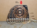
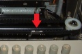
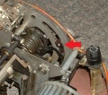
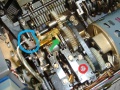
With the machine in Local mode, first step is to see if the distributor is spinning and if it is look for an armature out of place in the distributor area. Red arrow points to tape reader armature in distributor area.

_and_TR_armature_(red).JPG)
Also check to see if the H plate is installed between the printer and keyboard.

Lastly, check to see if the keyboard is resetting or if the reset lever is moving up and down.

File:Kybd reset lever in reset position (green arrow) and spring (red circle).JPG
You can hold the lever down and see if that stops the distributor from spinning and clears the running open problem. If so, the H plate may need adjusting or the printer may not be fully in the 4 rubber mounts it sits in. Lots of visual checks before doing the H plate adjustment.
If the distributor is not spinning, check all three fuses in the UCC-6 fuse bank. If all are good, exercise the keyboard Break key a few times. Also check to see if the keyboard Break vertical contact wire is out of place or dirty where it touches the horizontal bar. It should touch the bar when the Break key is not depressed.

If the machine is still running open, insert a screwdriver or a wooden clothespin half split to about 1/3 its size as show in pic. If the machine is still running open there is a problem in the mainshaft. The clothespin or screwdriver simulates current holding the selector armature closed. If the running open stops, the problem is electrical. Be careful not to dislodge the little copper leaf spring on the armature held on with two small C clips.

One more test to isolate the running open issue. Place the machine in Line mode and apply a 9 volt battery to pins 7 and 8 of P2 in the Molex bank of the UCC-6. If the printer still runs open reverse the polarity of the battery leads. If the running open stops, the electrical issue is in the Local Loop supply. The SMD card and power transistor are good and the likely problem is the large flat green resistor in the UCC-6.

If the machine is still running open, the issue is in the UCC-6 and you can resume testing in Local mode. It may be a bad solder joint on the vertical SMD card, defective SMD card, or the power transistor that sends current to the printer selector magnet may be defective.
Check the SMD card for bad solder joints and more troubleshooting in the UCC-6

Green resistor, Local loop capacitor and power transistor hidden in UCC-6 pic.

The above work is probably good 95% of the time but anything that can go wrong will.
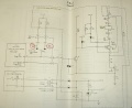
Some schematics to help below.


Resources
Manuals
Tools and supplies
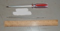
Printer removal tools
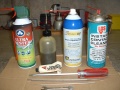
Basic products used in 33 work
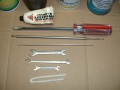
Basic tools used in 33 work


