Imsai 8080
Imsai 8080 S-100 computer. The original on top, and retrofitted with a hexadecimal front panel from Wameco on the bottom (Dad's Imsai)
See also; Imsai Floppy Disk
Contents
The Money Shot
The Money Shot as in how way to much money I spent to get these drives and the FIF FDC set. I now have four of the Calcomp floppy disk drives and an FIF FDC. Get ready, set - restore!

Dad's Imsai
This was my dad's computer. I recently rebuilt the power supply of dads original, I bought another Imsai computer off ebay to house the Wameco hexadecimal display front panel. I sent both of these front panels out to System Glitch for repair. I did the mechanical reinforcement of the switches on the Wameco FP1.


Images

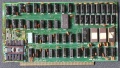
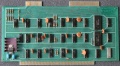
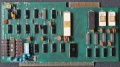
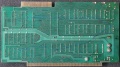
Pictured with original 8080 CPU card, an unknow manufacturer 8k RAM board and Martin Eberhard's post era 88-2SIOJP I/O and EPROM board.

FIF / VIO evaluation - restoration
I paid entirely to much on ePay for an Imsai 8080 but included FIF FDC board set with both the IFM and FIB boards as well as the interconnect ribbon cable and the ribbon cable to the drive enclosure. It came with an Imsai eight inch FDD cabinet with identical drives to the set I already have Imsai Floppy Disk
See also; Imsai Floppy Disk
VIO
Udo Monk has a very nice video z80 pack simulation of the VIO
VIO front
VIO rear


FIF
FIB Front
FIB Rear
IFM Front
IFM Rear


SIO


SIO test echo code
; jsio.asm jha 8/2/2018 testing sio
; https://wiki.theretrowagon.com/wiki/Imsai_8080
; Originally from a Monitor program code by John Garza hence the EQUates
; http://jgarza.sdf.org/files/M72.ASM
;
; Important init code from VCF forums
; handy VCF threads for configuration
; http://www.vcfed.org/forum/showthread.php?64964-Imsai-FIF-FDC-project
; http://www.vcfed.org/forum/showthread.php?37137-How-to-get-output-from-SIO-with-Intel-8251A-USART
;
; uses a straight through cable.

;------------------
;IMSAI 8080 EQUATES

LEDS	equ	0FFh	;IMSAI front panel output LEDs (top left)
SWCH	equ	0FFh	;IMSAI front panel input switches (left)

; channel a
;TTS     equ     03h     ;SIO channel A command port
;TTI     equ     02h     ;SIO channel A data port (yes input=output)
;TTO     equ     02h     ;SIO channel A data port

; channel b
TTS     equ     05h     ;SIO channel B command port
TTI     equ     04h     ;SIO channel B data port (yes input=output)
TTO     equ     04h     ;SIO channel B data port

TTYDA   equ     02h     ;tty data available (ready to receive?)
TTYTR   equ     01h     ;tty terminal ready (ready to transmit?)

    org 0100h
init:
    mvi a,0
    out TTS
    out TTS
    out TTS
    mvi a,040h
    out TTS
    mvi a,04eh  ; 8,1,n
    out TTS
    mvi a,037h
    out TTS

inout:               ; loop read from serial, write it to serial. Serial terminal echo.
    in TTS
    ani TTYDA        ; DATA available?
    jz inout
io1:
    in TTS
ani TTYTR           ; ready to receive?
    jz io1
    in TTO          ; read character
    out TTO         ; write
    jmp inout       ; repeat
    end
MIO


Not pictured
- (2) Vector Graphic 16k static RAM vev 1
- Microbyte Memory M32KSS Rev a 32k RAM
- Potomac Micro-Magic Inc. MM-103 Modem (Base port address C0)
ImageDisk
See Imagedisk page on this system for notes on my imagedisk usage to create boot media.
Resources
- EZBOOTS.ASM ezboots.asm Automatic bootstrap simulator for starting cp/m
- ABOOTSIM.ASM Like above but with error handling.
- IMSAI 8080 at Wikipedia.
- autometer.de Udo Munk stuff Lot's of Imsai goodies here.
- Kenneth Vaughn has some videos of the PCS-80
- IMSAI 8080 Feb 1976 Catalog
Manuals
- SIO2-2
- 8080 Manual
- PCS80-30 Users Manual
- VIO Manual
- MIO Rev 2
- IMSAI Schematics
- Imsai FDC notes and .ASM
- IMSAI CPM System Users Guide Version 1.31 Rev 2
- Imsai keyboard manual
- Tanner 64k Static RAM Digital Research / Tanner / Coex manual
Found at http://www.bitsavers.org/pdf/imsai/
- CPM System Alteration Guide for IMSAI CPM Version 1.31 1977
- SHAKDOWN Disk System Diagnostic Users Guide 1977
- CPM Interface Guide 1976
- IMSAI Floppy Disk Operating System DOS-A Mar77
Purchased August 2018
Purchased from Herb Johnson www.retrotechnology.com
Schematics
I believe these came from Josh and/or other members of the S100computers Google group.
- IMSAI FP Schematic
- IMSAI CPA from Josh Bensadon
- IMSAI MPU
- IMSAI RAM
September 2018 S-100 Prius Road Trip
Huh? Prius road trip? I'm documenting some hardware I got on a road trip. And some forensics to try and use some parts in other projects.
Parallel ASCII Keyboard


Looking at the edge connector and the DB25 and header connector note that the two wires were connected to the Processor Technology header. I assume for DC voltage. I put some blue ink on one of the insulators so I could chase it in the details, I noticed that one wire is red striped although it was in the middle of a ribbon cable.
Processor Technology 3P+S, I/O Rev a on this wiki